3D Parametric Design and Slicing for Laser Cutting
Conceptually, transforming 3-dimensional forms into a set of 2-dimensional curves for laser cutting is simple. To do so, we first construct a series of planes from the bottom to the top of the object, and then we take the boolean intersection to get a series of slices from the object. We can then move these slices onto the XY plane and space them out to prepare for cutting. In this post, I will be going over an example implementation of this slicer using Grasshopper. For the purposes of this assignment, I have decided to parametrically generate vases to be inputted into the slicer.
Materials
6 millimeter acrylic sheets provided by the BTU Lab were used for the laser cutting. The amount of acrylic needed was dependent on the width and height of the parametric design.
Designing Parametric Vases
A vase is a simple object that consists of an exterior and a hollow interior with a single opening at the top. I wanted to generate a variety of vase designs with ease, so I planned for a series of polygons to be placed at different heights and connected along the z-axis, with each polygon’s individual parameters being alterable. The Loft function in Rhino and Grasshopper is used to connect the polygon curves to each other.
Here are all the tunable parameters for the vase object
- Number of polygons (3 - 10)
- Distance between successive polygons
- Cutout size to control size of hollow volume
- For each polygon:
- Radius (10.0 - 15.0)
- Number of edges (3 - 10)
- Fillet radius (0.0 - 7.5)
- Random seed for Python script
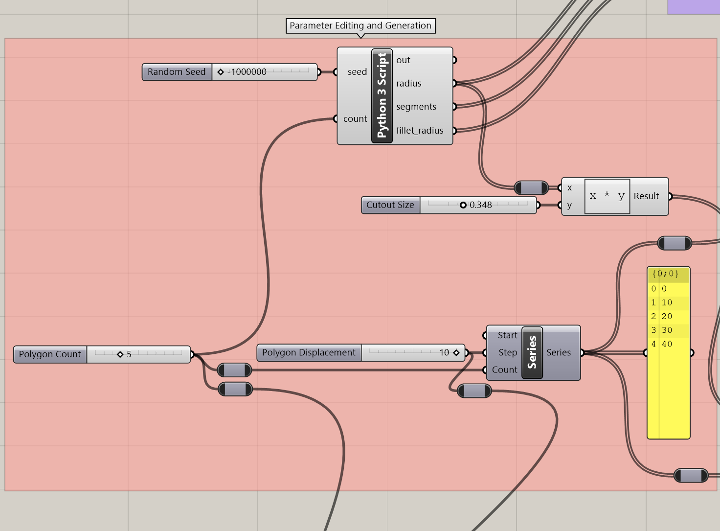
Because I didn’t want to manually edit every polygon’s parameters whenever I wanted to change the object, I decided to write the short Python script shown below to handle random generation of these values.
In Grasshopper, the unknown variables in this script are inputted and outputted via the visual scripting language. As you can see in the image below, these parameters are passed in and out of the Python 3 Script component.
To construct the geometry necessary for a vase, a lofted tower of polygons forms the exterior, and a cylindrical volume is taken out of the center of the object. Both the polygon tower and the cylindrical volume cutout are scripted in the below images. Both geometries are built using the same starting parameters (e.g. radius).


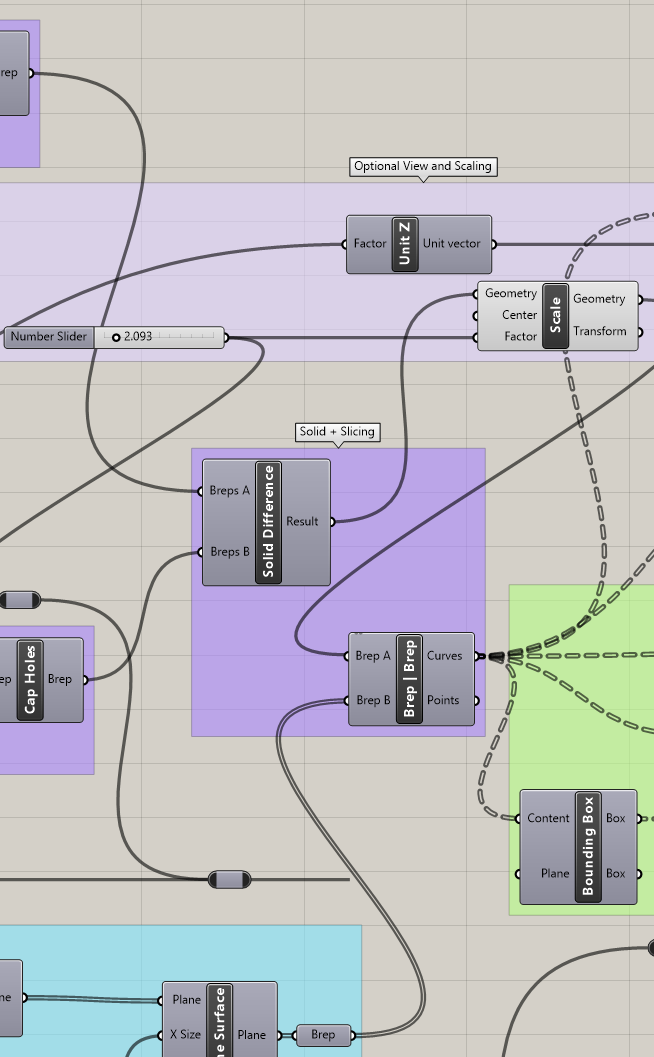
Following this, we can use a boolean difference to leave a vase-like structure, with the cylindrical volume hollowing out the polygon tower. The Solid Difference component in Grasshopper does this for us. There is a lot going on in the below image. The group being shown is the core of the algorithm, creating the vase solid as well as slicing it, which will be clarified in the next section where I go over the construction of the slicer.
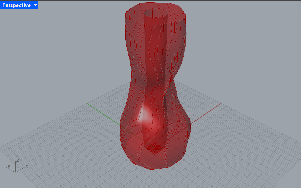
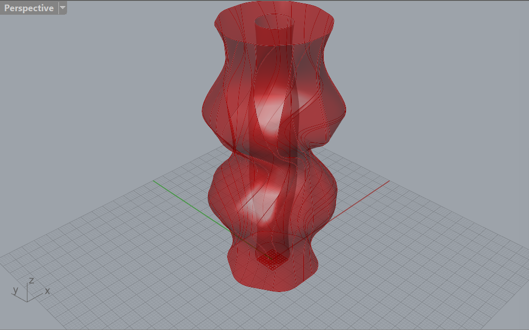
Example Parametric Vases
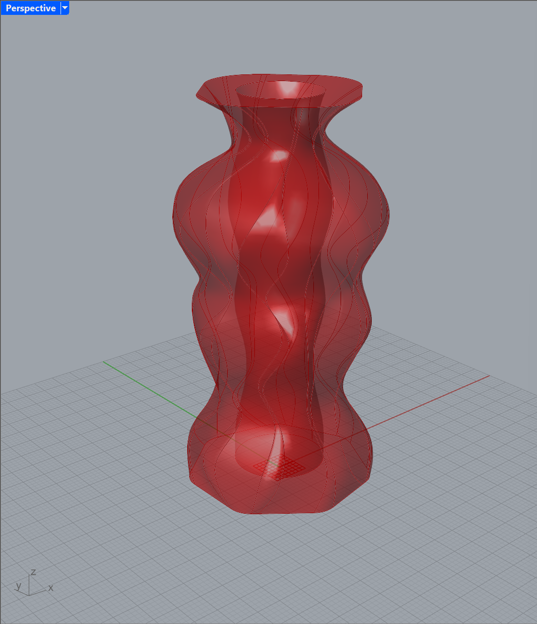
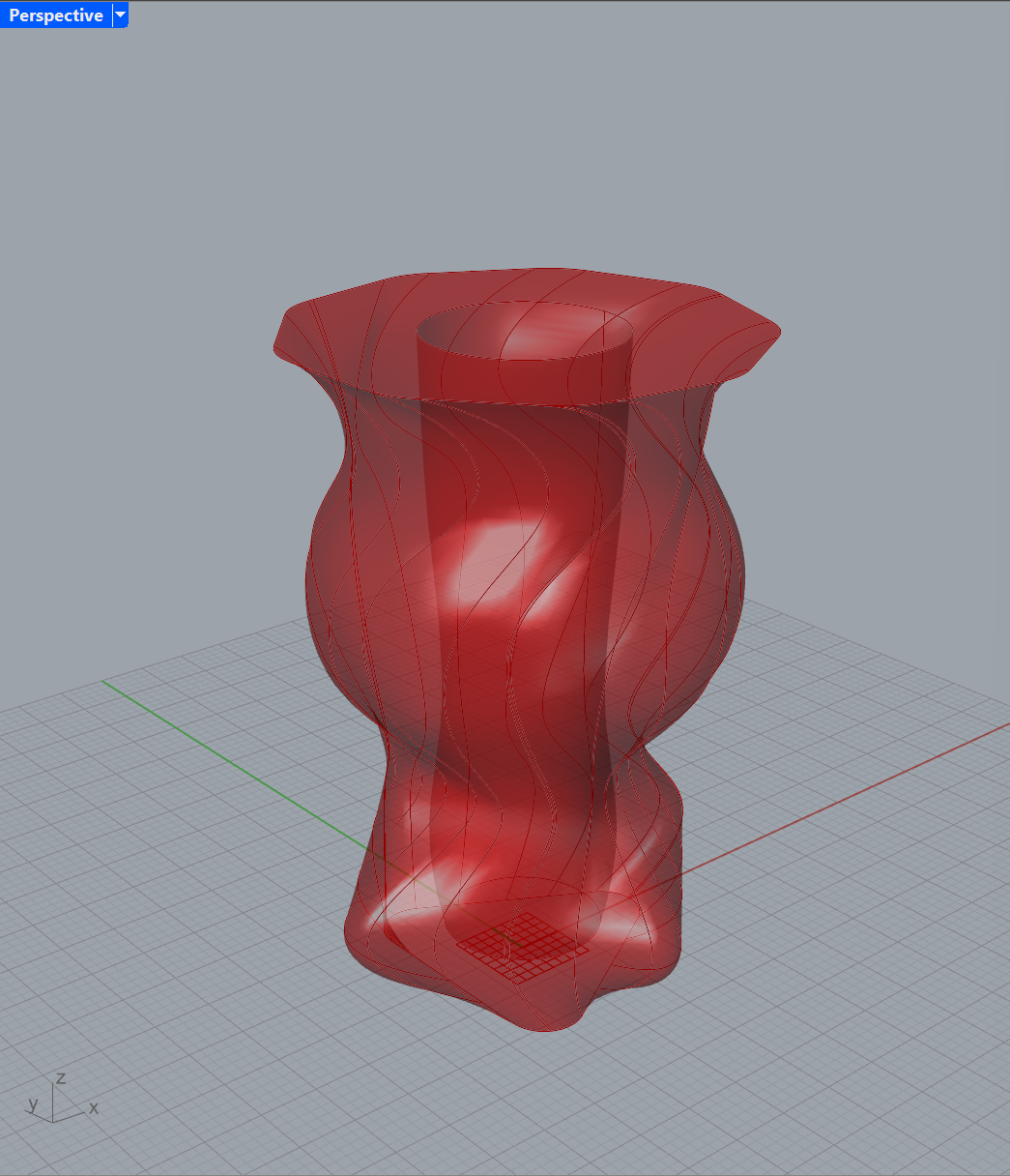
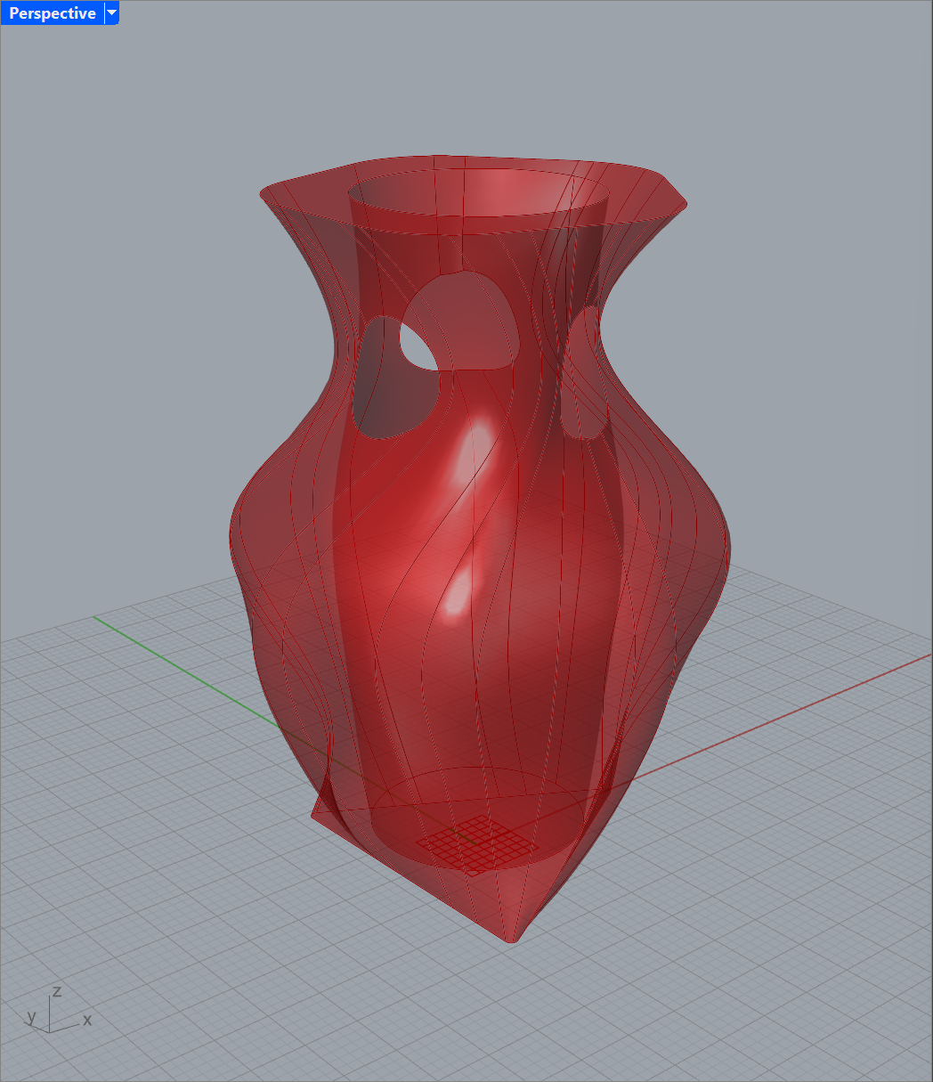
Slicer
To slice the model into sections that can be cut, we first construct a series of parallel planes up through it. These planes are separated by a distance determined by the material thickness in millimeters.

The result is passed into the previously shown intersection component to generate the slices for the object. Then, this data is passed forward into a series of functions that move the resulting curves onto the XY plane and spread them out in preparation for cutting. Another Python script is used here to parse the data tree of curves and generate lists of displacements for each one. There is probably an easier way to do this, but since I had a hollow cutout curve in addition to the main form curve, it wasn’t that simple to figure out. Some slices (namely the first one at the base), only had one curve, and others had two, which meant that the curves had to be carefully displaced so that they stayed with their associated curve. The script also helps compute the distances between slices on the XY plane based on the bounding box widths of each of the curve groups. This keeps the slices as close to each other as possible without overlapping. A basic print statement during the loop also outputs the index text into the following section, which is used for numbering the slices.

Finally, text numbering is added onto each of the slices to aid in assembly afterwards. This text can be displaced in the x and y directions to make sure it fits on every slice without falling in the hollow section of the vase slice.

I put together one other group of components to help with scaling the object and viewing how the 3D form might look after assembly. A simple extrusion of the slices allows us to see the discretized version of the object that we will end up gluing together after cutting. The extrusions extend for a distance equal to the material thickness.

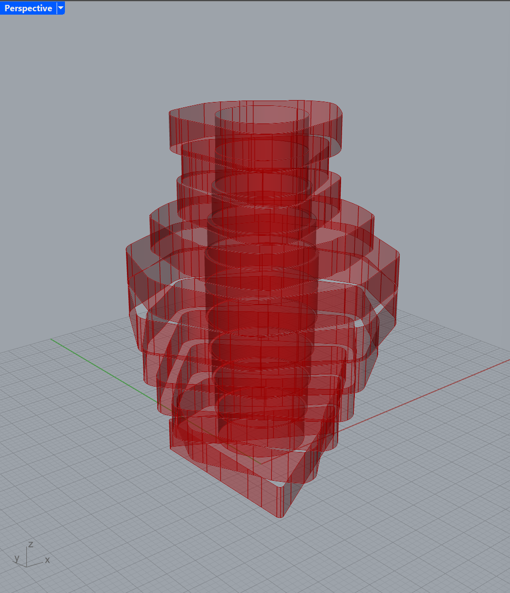
The full Grasshopper script can be downloaded here.
Fabrication Results
Design 1

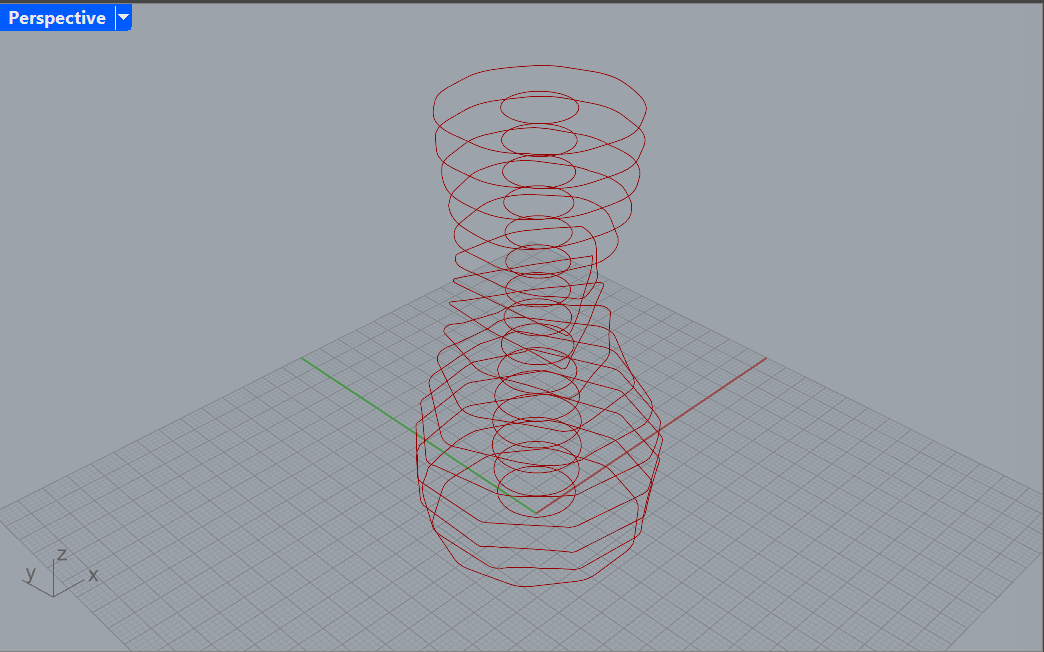

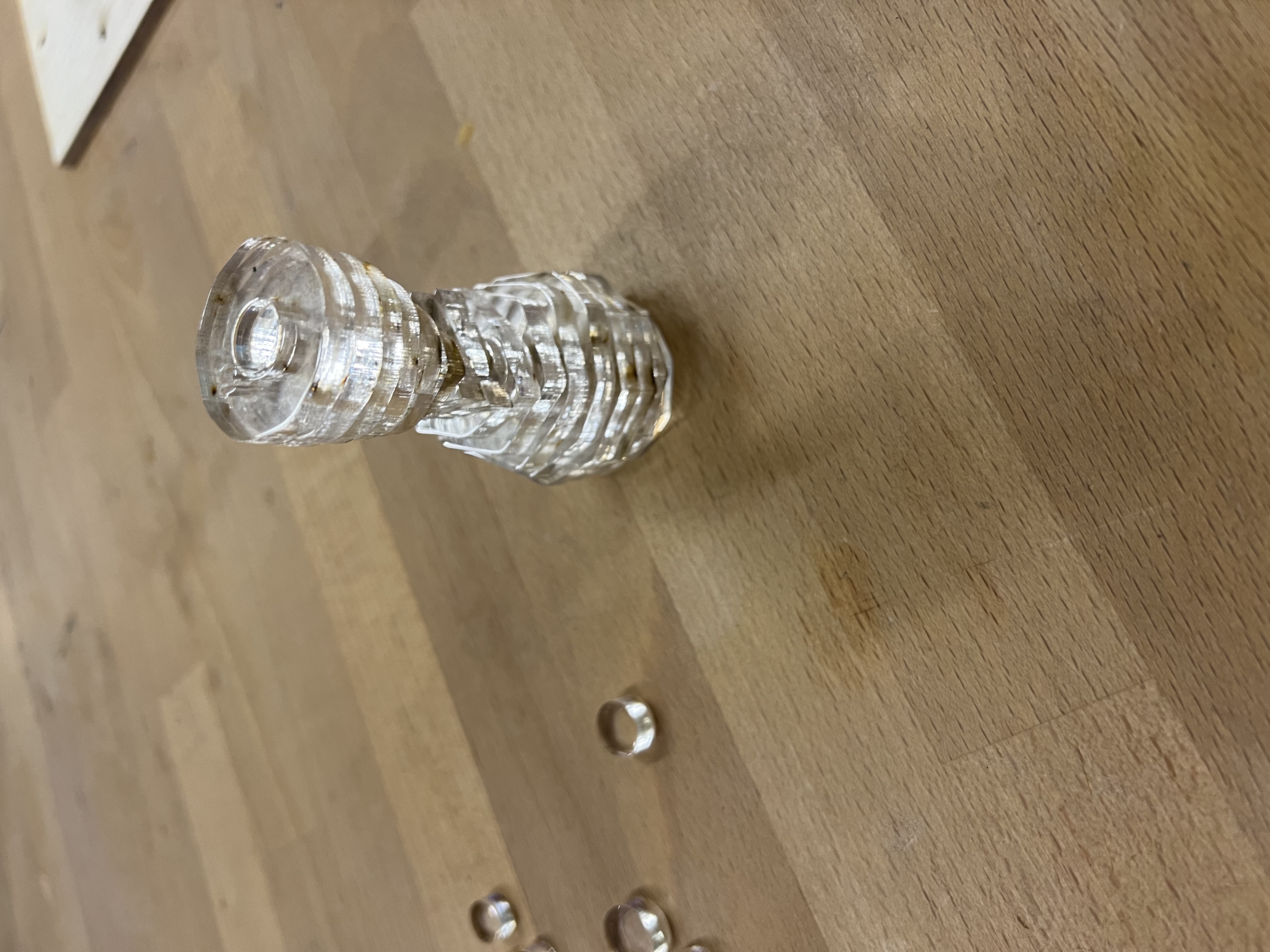
Design 2

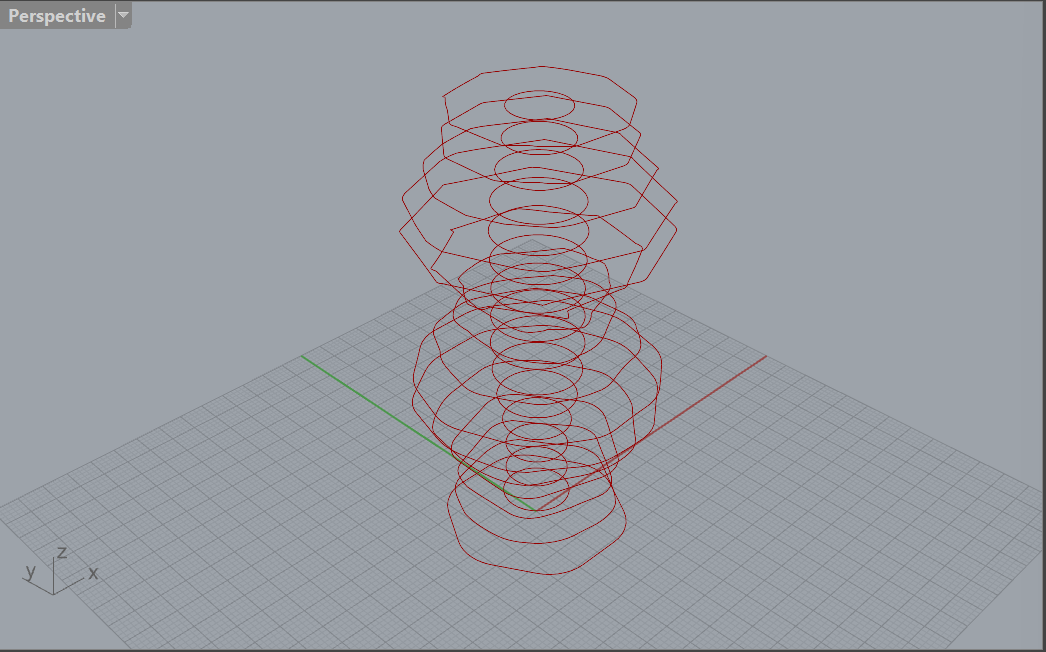
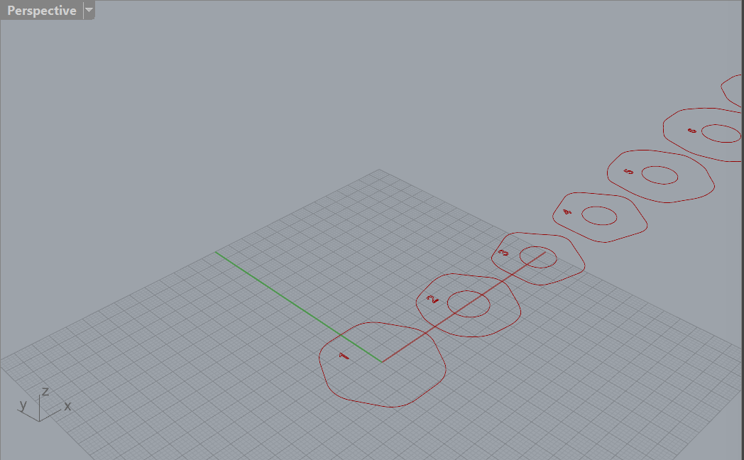
Conclusion (and Problems Faced)
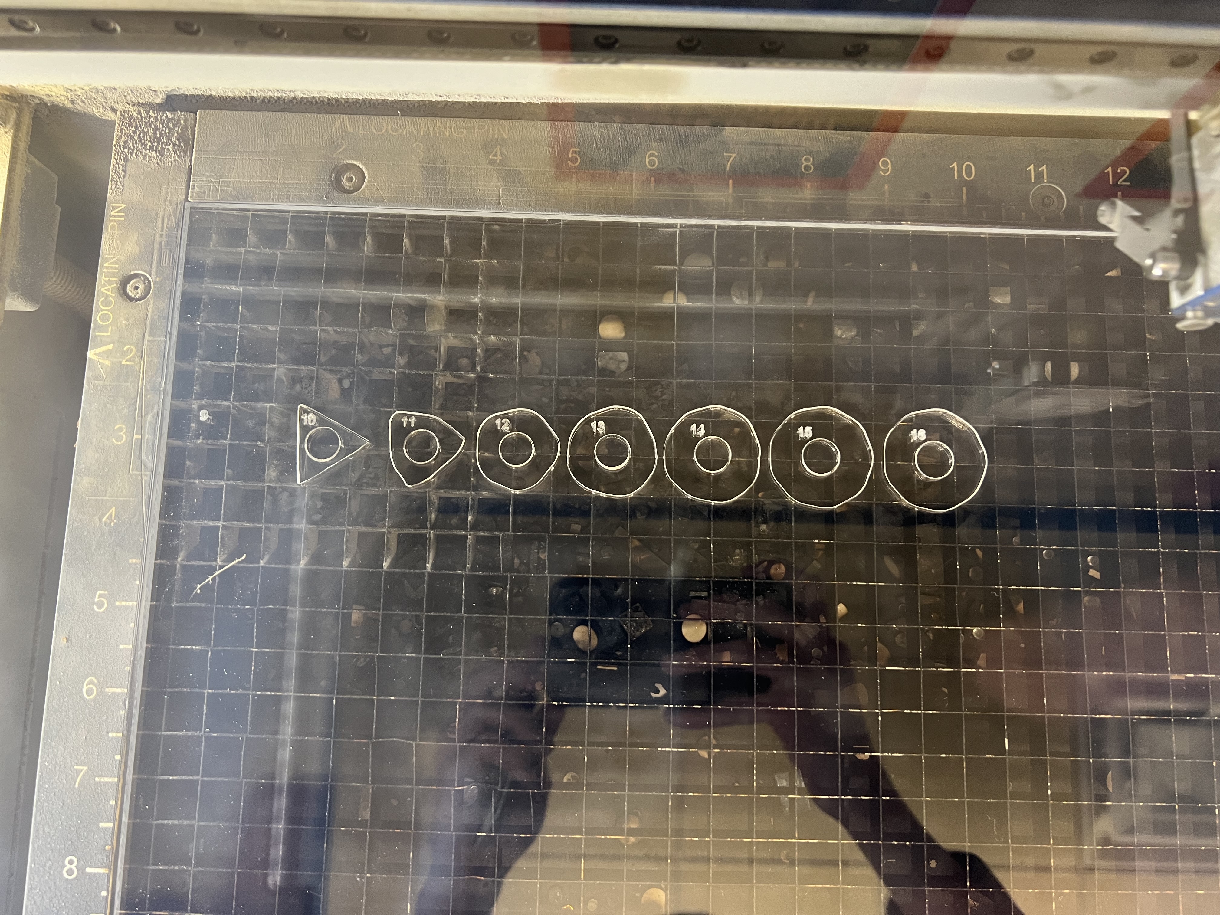
One issue with this fabrication process was the size of the cuts. If I went too small, then the numbering on the slices would be illegible, but I wanted to conserve material as much as possible. I ended up going with slice dimensions maxing out around 40 millimeters. This allowed enough space to place numbers that were slightly larger than 4 millimeters, which was about the limit of precision for the laser cutter.
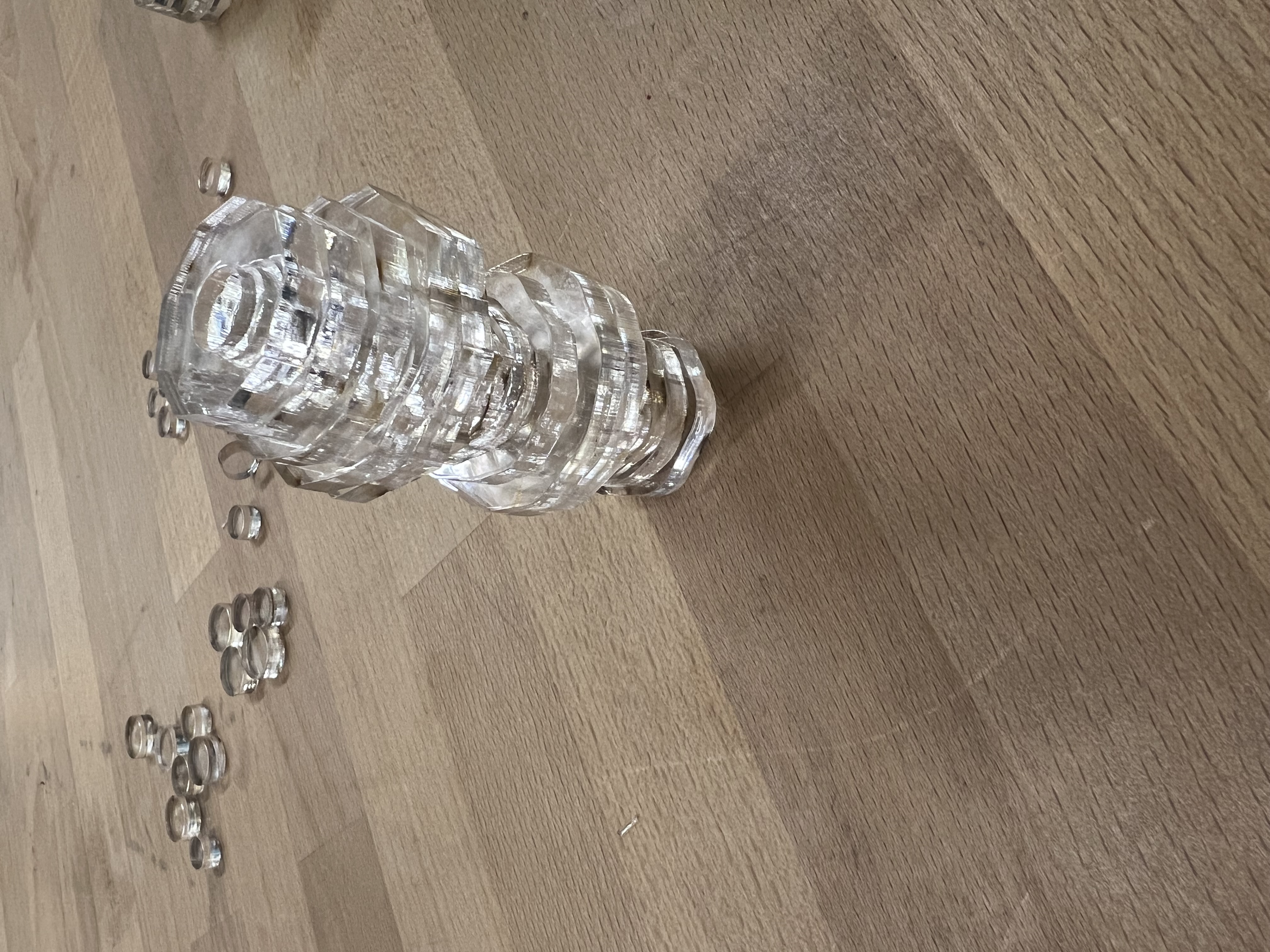
Gluing the slices together was also tedious and inaccurate. A better method would involve fabricating joints between the slices, which would be an interesting direction for a future project.
In the end, I was grateful to myself for having programmed the slices to be spaced correctly on the XY plane through Grasshopper. This made the transition to cutting much smoother. I had to move some slices onto another row to fit the available material on the cutting bed, but that was pretty much it.
